The Moving target range
For better shots.
Design
This project started from a need to learn to code microcontrollers and some mechanical design. It was interesting to see what could be possible to implement with an 8-bit microcontroller. Also having a moving target range improves shooting skills for competitions.
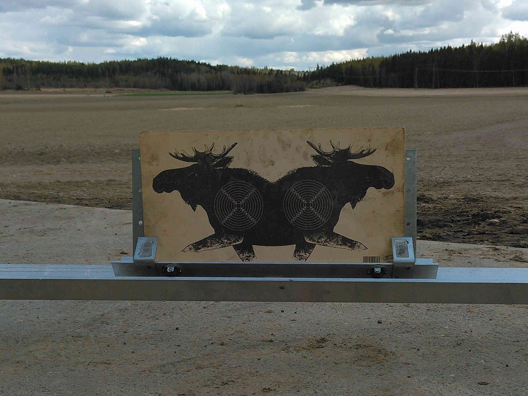
Figure 1 Target in its sledge on rail.
To keep the mass down material of the rail was chosen to be aluminium. The length of the opening is 2 meters and as such the length of the rail was 3 meters. It was somewhat challenging to transport the aluminium profile in a small Honda Civic.
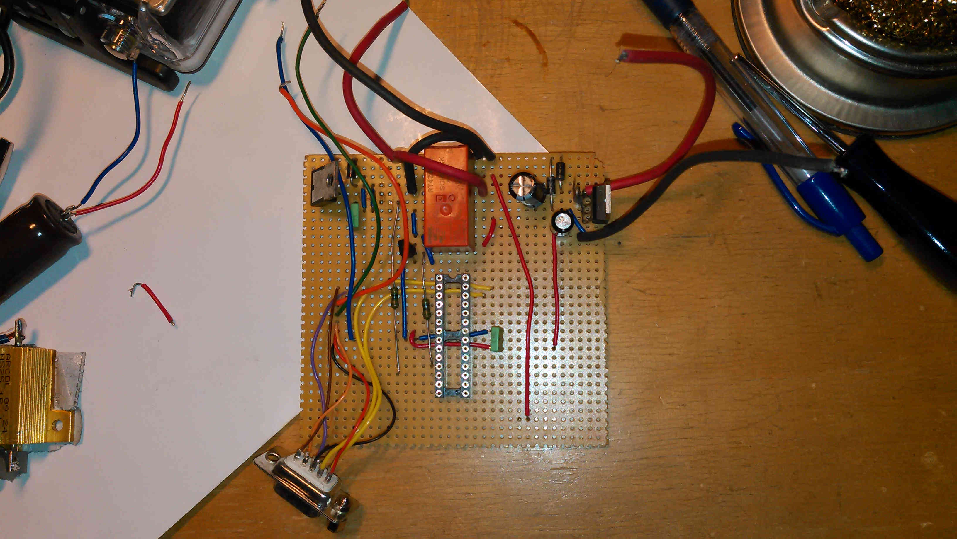
Figure 2 The circuit board with some components.
To enable fast prototyping the circuit was realized on a veroboard. Drive direction is chosen with a 12V relay. The more durable solution would have been a H-bridge. However, it is likely that the manufacturer's guaranteed maximum number of switchings is not exceeded in any time soon.
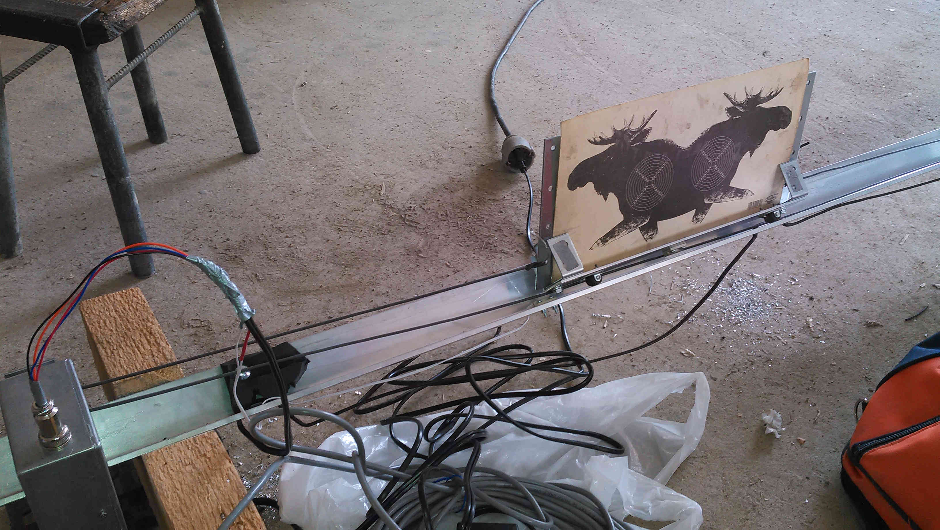
Figure 3 Motor and drive system.
The motor was taken from a cheap battery driven drilling machine (Kätsy Kalle 16.90 euros from Tarjoustalo for those who are interested). I wouldn't recommend using the machine for drilling though. A brand new replace motor with better characteristics would cost at least 60 euros and therefore this was a cost effective solution for a prototype. Although I do still have figure out usage for the battery cells.
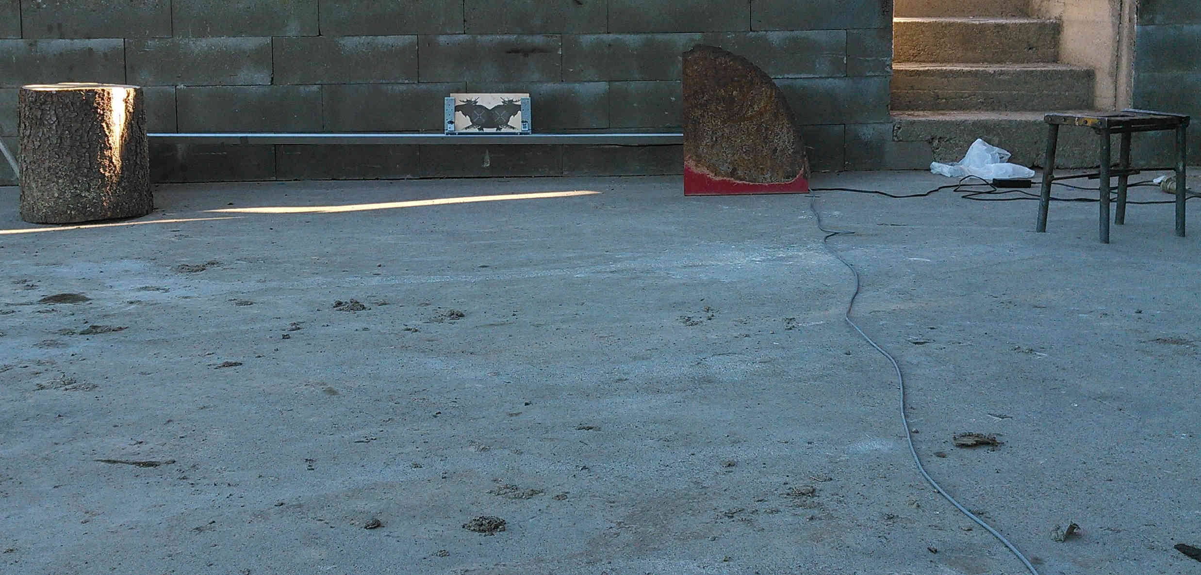
Figure 4 First shooting trial.
Once I got the drive train functioning it was time to test the range. I found some protective objects to prevent hitting the motor. I soon discovered that I needed a start delay to be able to press the button and raise the air rifle in time.
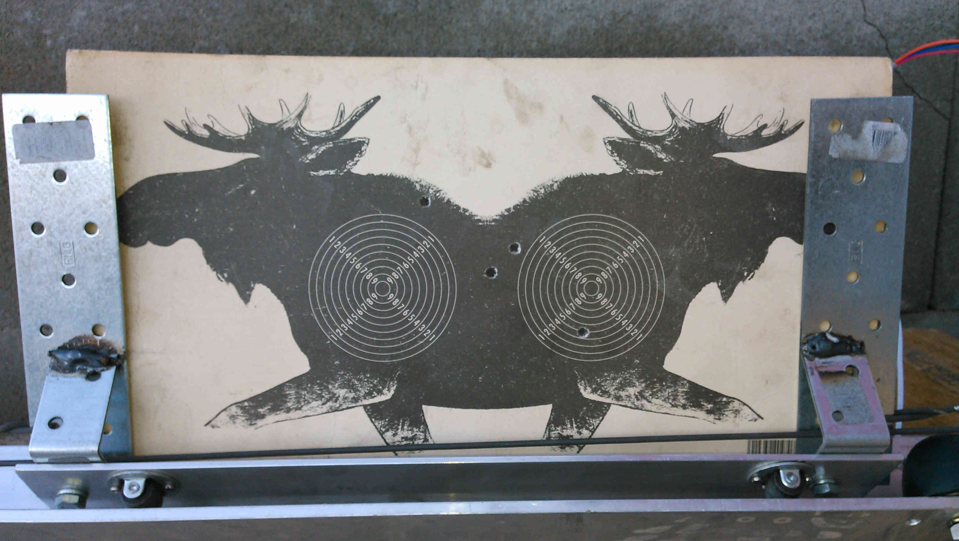
Figure 5 First result.
As stated above the speed of the range was a bit too fast and therefore most of the shots were of the target. However, it felt satisfying to get the target moving after years of building and designing. The biggest challenge for the electrical engineer was obviously the mechanics.
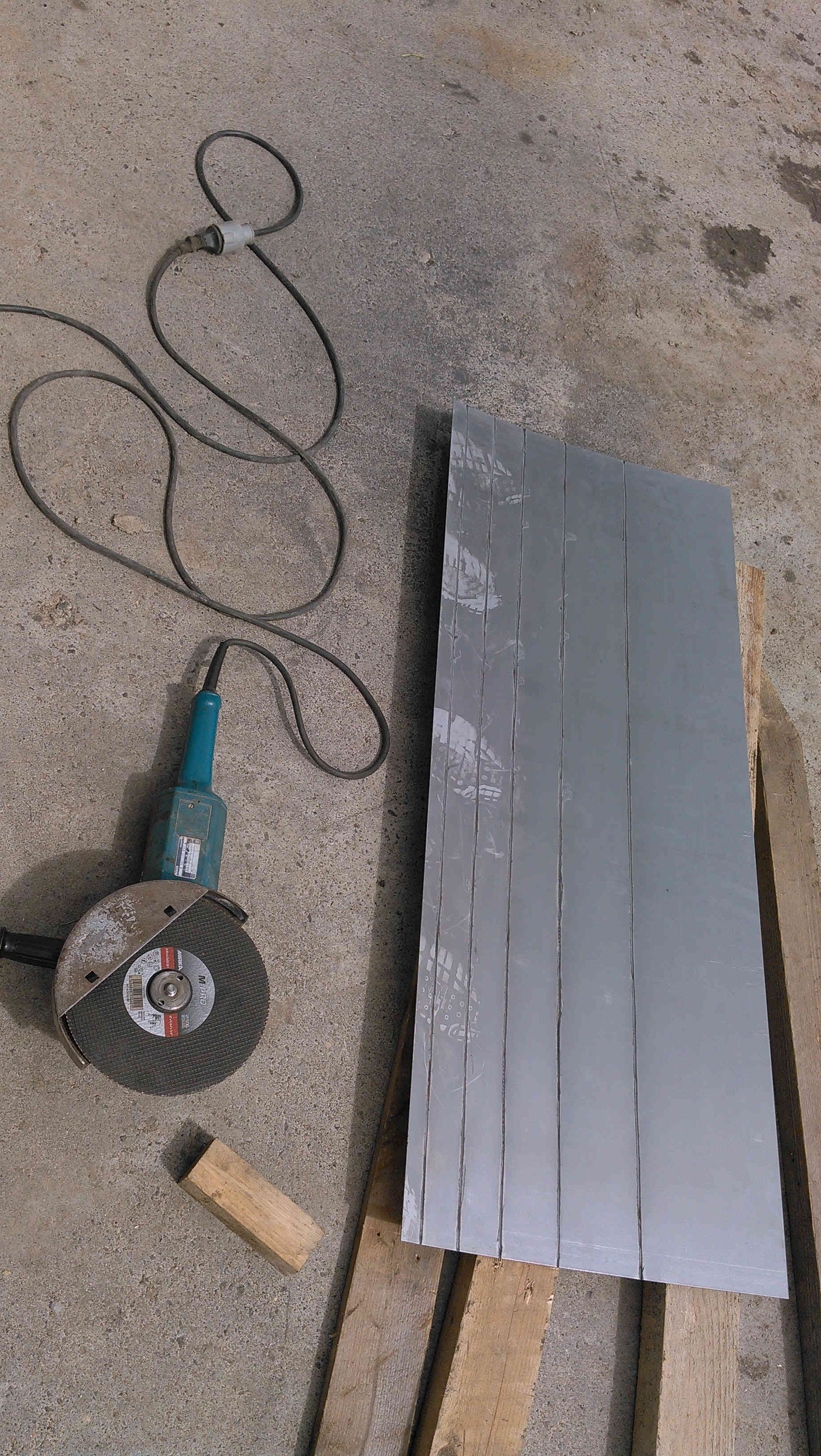
Figure 6 I needed to carve a groove to aid the bending.
After getting the mandatory trials off the table, it was time to start building the bullet collector. I managed to find a steel plate of 1.5 mm from a local reseller. The size of the plate was 1250 mm x 500 mm and I was obliged to design the bullet collector little differently than I would have wanted.
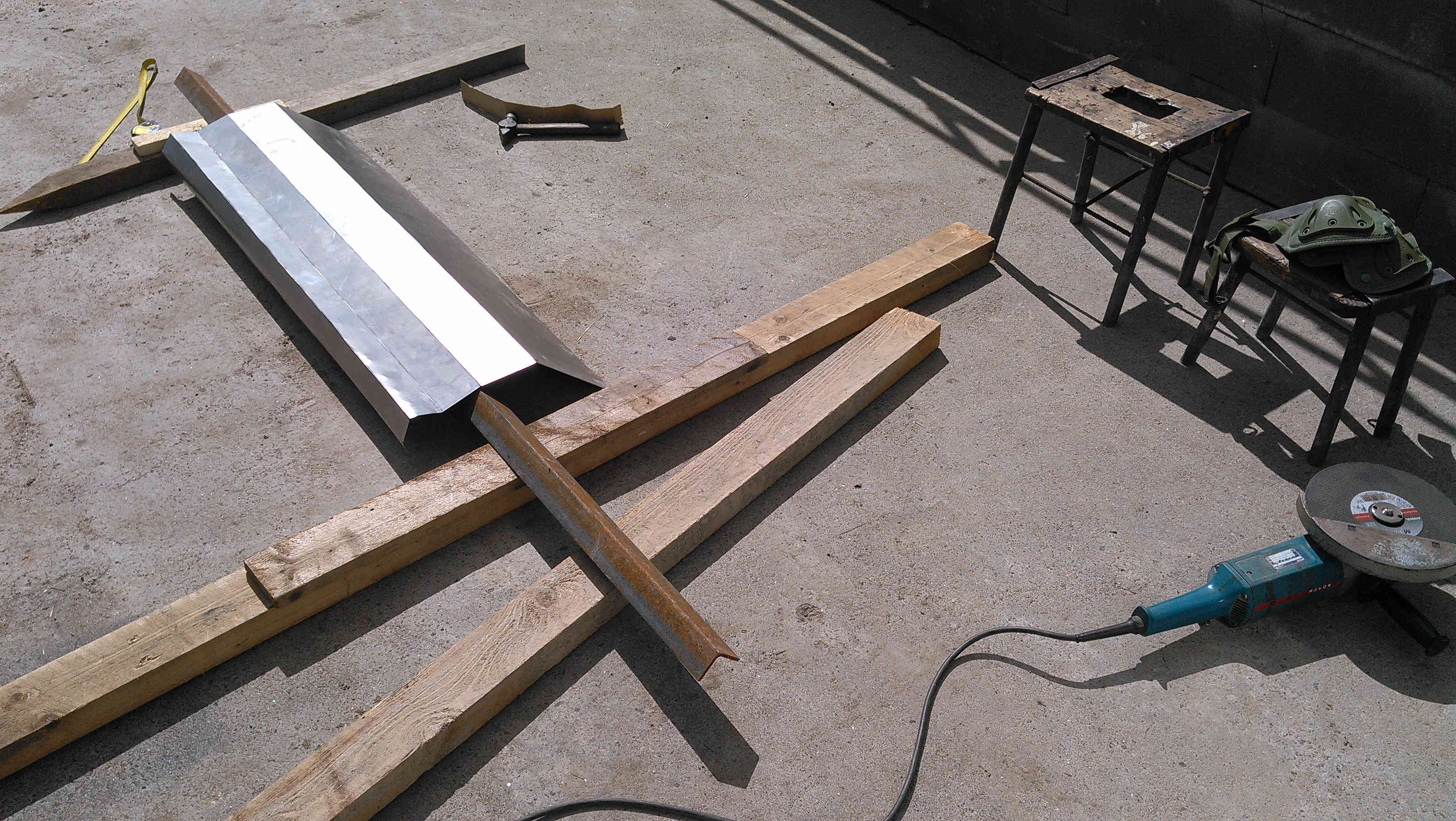
Figure 7 Bending a steel plate.
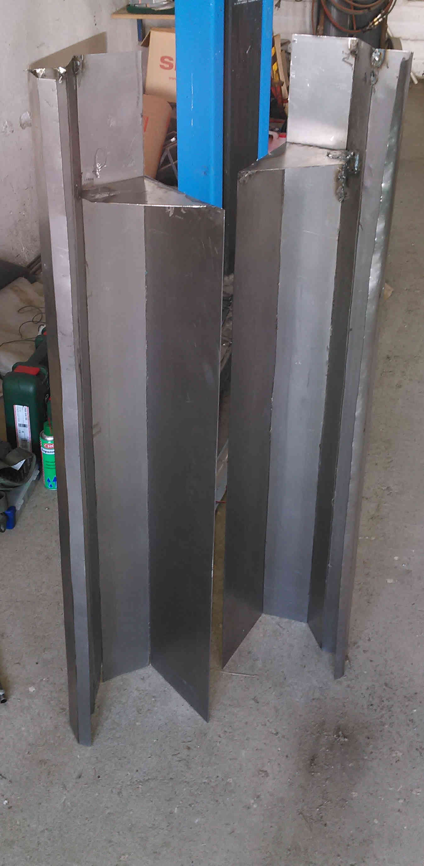
Figure 8 Finished bending.
Here are the two parts of the bullet collector after bending exercise. Perhaps not the most beautiful sight but good enough for my purpose.
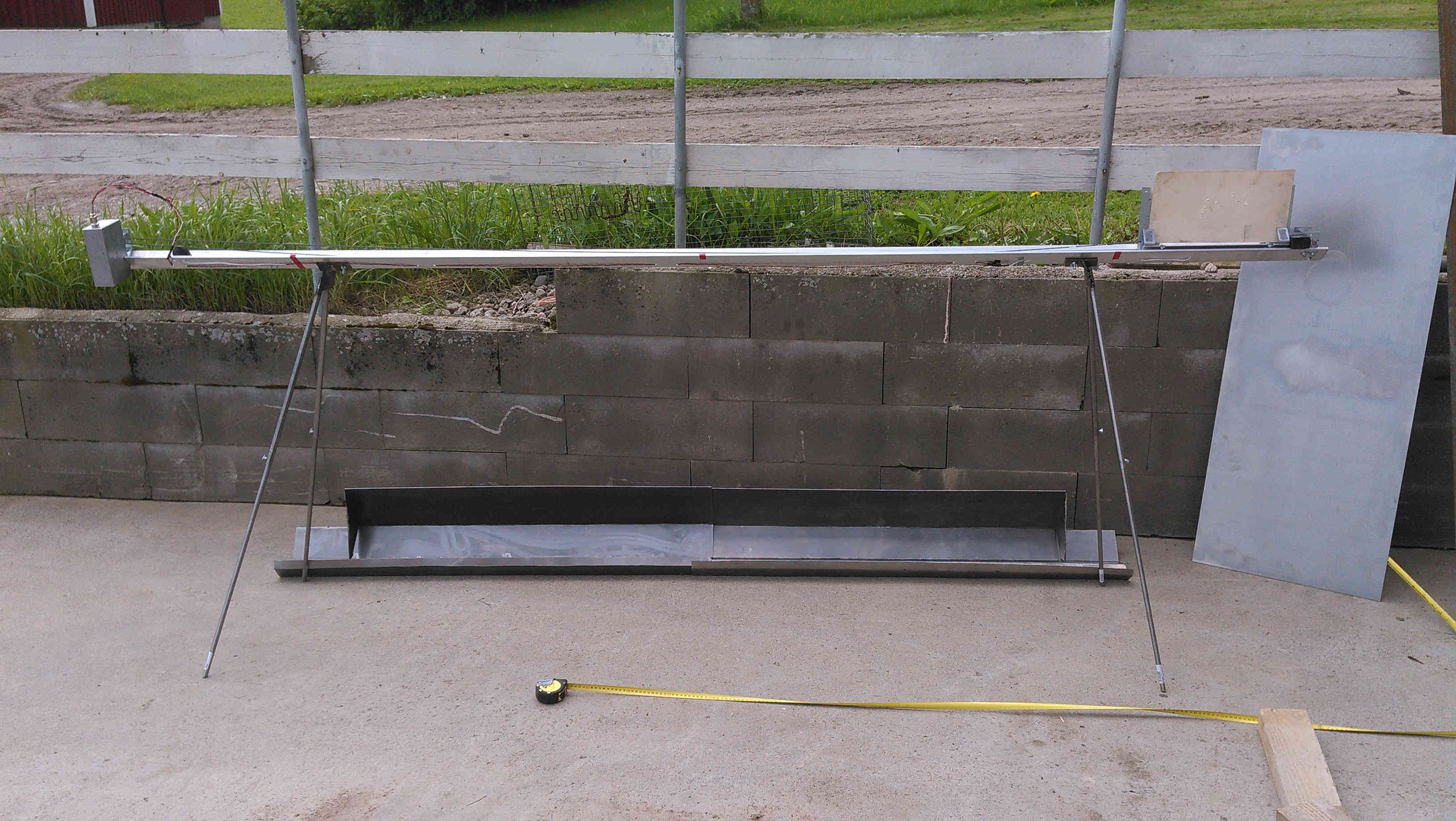
Figure 9 Last minute check of the length.
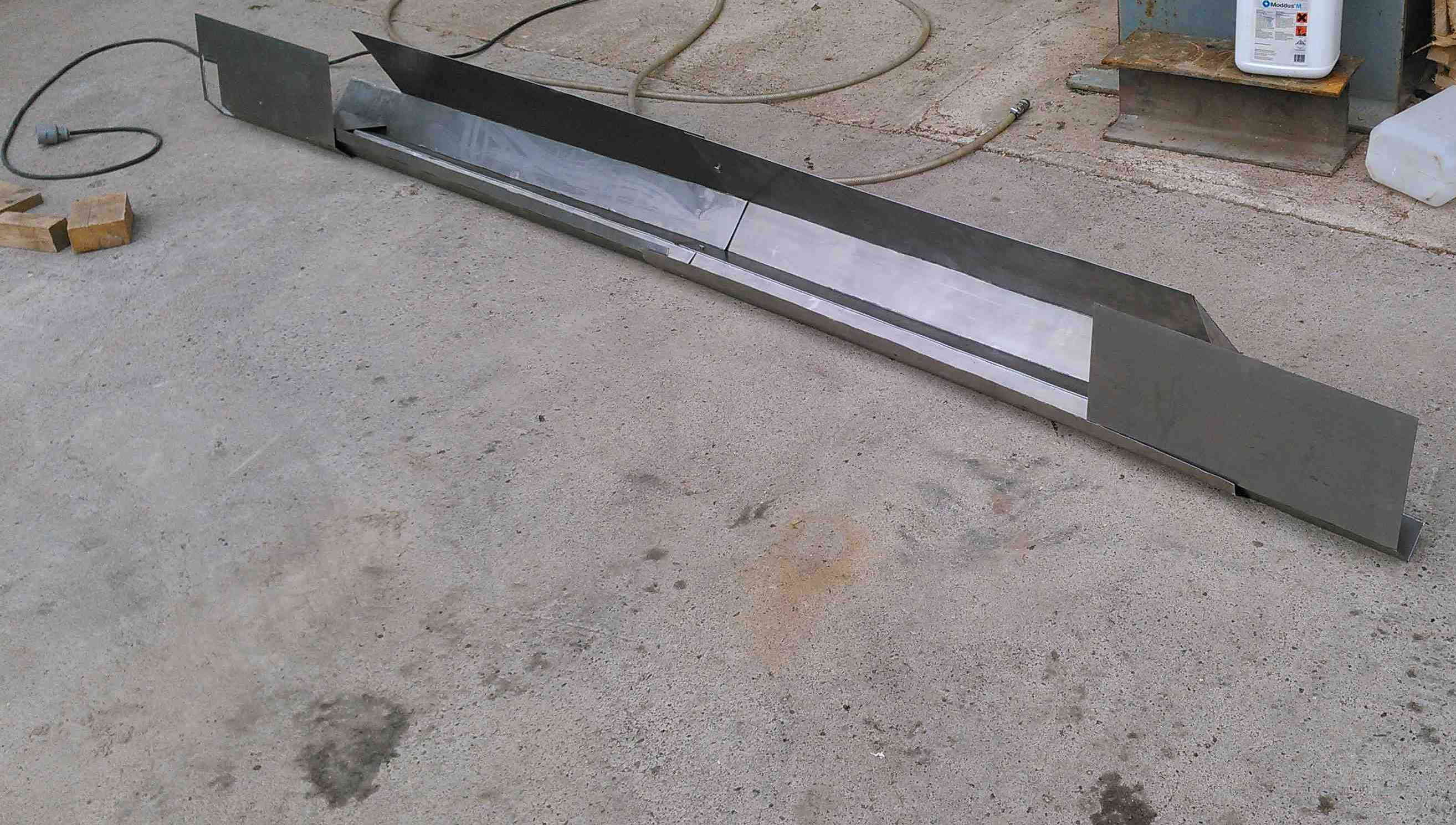
Figure 10 Ready to be painted.
After getting the last shields figured out it was time for try painting. At this stage I was content with the result even though I could already point out some ways to improve the design.
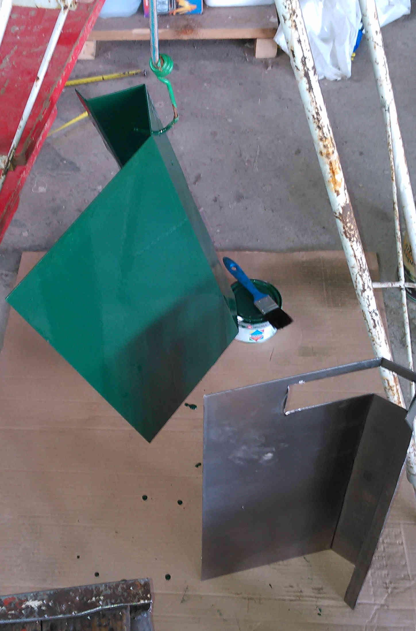
Figure 11 First paint tests.
I found the paint from a sale shelf and it turned out to be more glossy than perhaps required. However, it seems to cover the whole surface of the steel thus protecting it from getting rust all over.
I wanted to be able to bend the legs of the range to ease transport. However, I failed to design enough sturdy structure to hold the weight of the range and therefore there is a small observable oscillation when the sledge stops. But for the time being the structure has worked so I have not had a compelling need to change it.
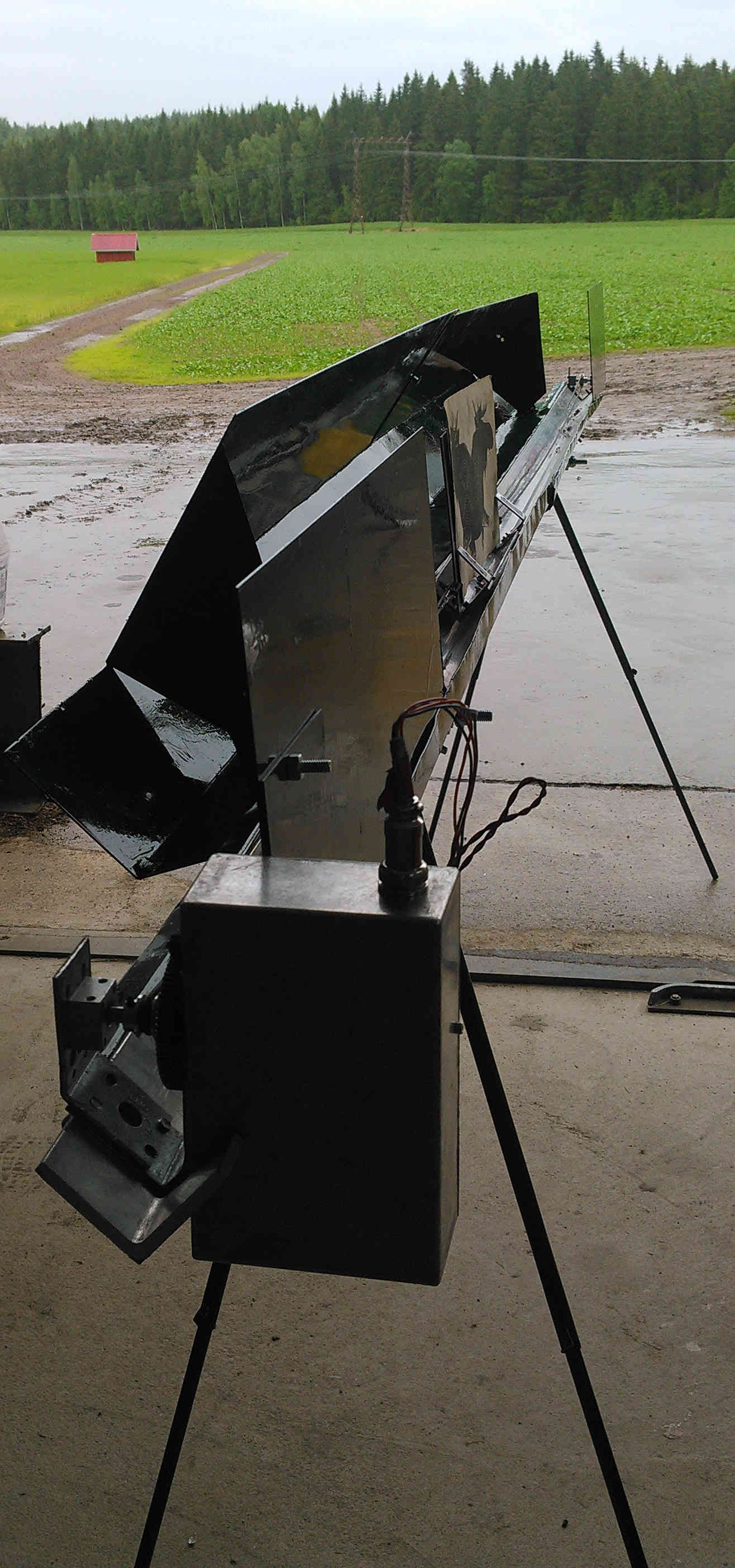
Figure 12 Waiting for the rain to stop.
The project was very educative as building such prototypes tend to be. I learned a lot from mechanical perspective as well as from electrical. I am satisfied how well the range works even though it is not always as reliable as one would want. :)